Week 9 Summary
For Week 9 of the HPS program, the participants were instructed on the various steps to take when performing a tolerance analysis. The first steps of this analysis would be to make a problem statement and make a tolerance analysis (TA) loop map to describe the effect each component has on the gap size expected in the area inspected. The next step includes listing the assumptions regarding how each component acts to adjacent parts and writing out the tolerance loop based upon how each component contributes to the upper and lower specification limits. The final two steps include making assumptions based upon the combined component tolerances and evaluating the results of the worst case and root sum square tolerance.
Tolerance Analysis Cases
I chose three different cases to analyze for my product for the tolerance analysis. Each of these cases includes an expected gap to account for. Below are the charts displaying the tolerance analysis of the three areas.
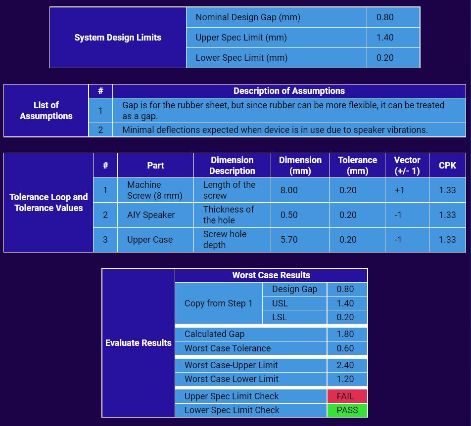
Tolerance Analysis Case #1
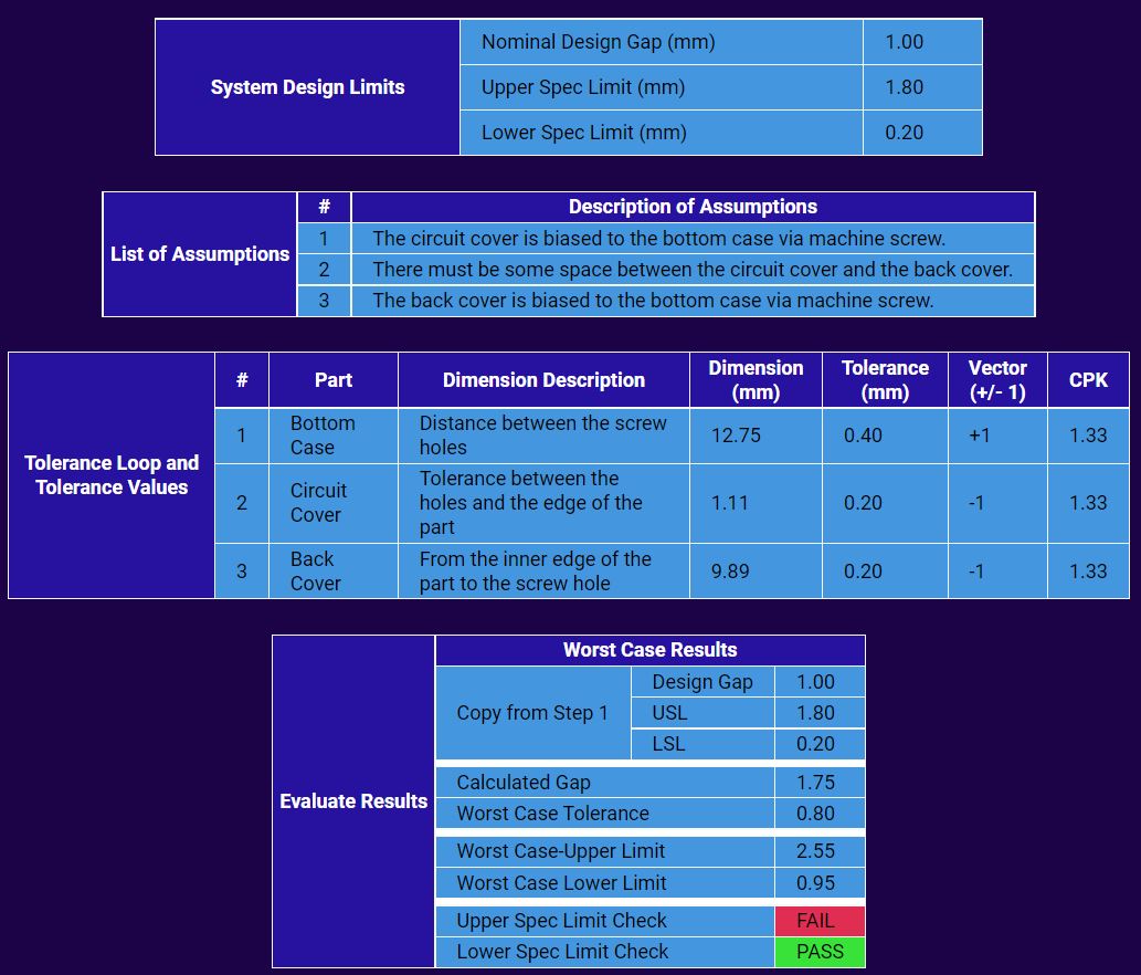
Tolerance Analysis Case #2
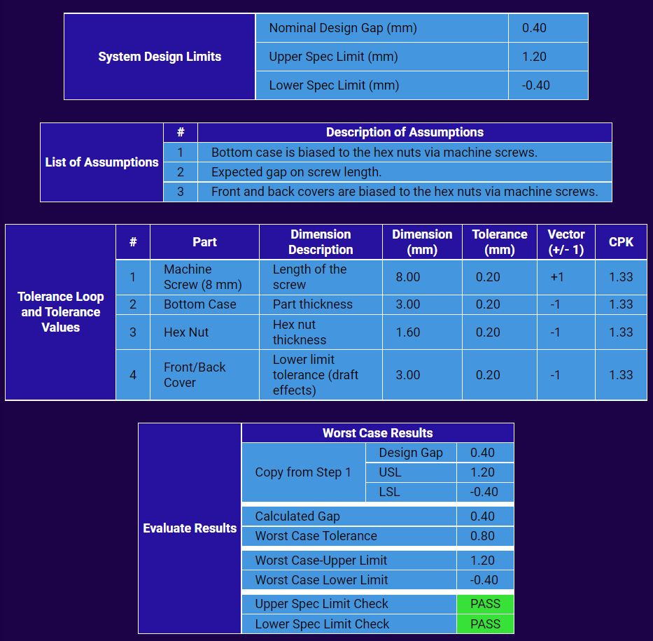
Tolerance Analysis Case #3