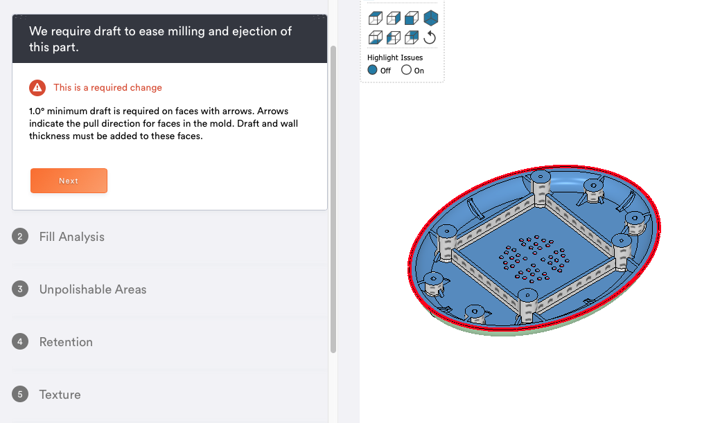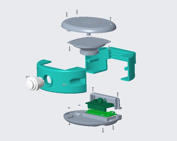
Standard Operating Procedure of Noisemaker
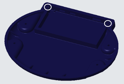
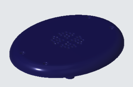
Step 1
Take the bottom case and orient it as shown in the photograph. Make sure to tap the screw holes in the rear where marked.
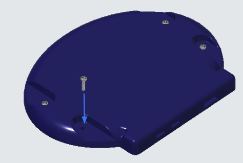
Step 2
Turn the bottom case around and insert the machine screws into the part as shown.
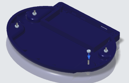
Step 3
Flip the bottom case around once more, keeping the machine screws inserted. Secure the machine screws with hex nuts.
Step 4
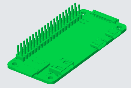
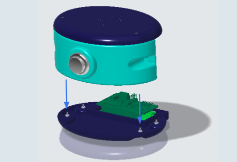
Get the Raspberry PI and orient the printed circuit board (PCB) as shown.
Step 5
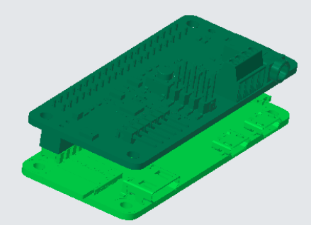
Grab the voice bonnet and attach it to the Raspberry PI using the prongs on the PCB.
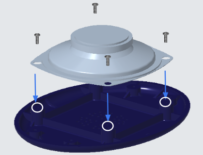
Step 6
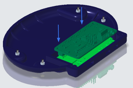
Insert the Raspberry PI and voice bonnet configuration into the bottom case as shown below, and make sure the fit is tight.
Step 7
Grab the upper case part and orient as shown.
Step 8
Take the speaker and four machine screws, and flip the upper case upside down. Tap the marked screw holes (all four), and then align the speaker and secure with the machine screws.
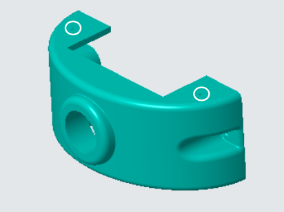
Step 9
Take the front cover and orient it as shown, and tap the screw holes on the top and the bottom.
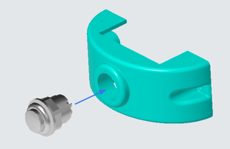
Step 10
Take the 24 mm button and remove the plastic hex attachment. Insert the 24 mm button as shown, and secure with the plastic hex ring.
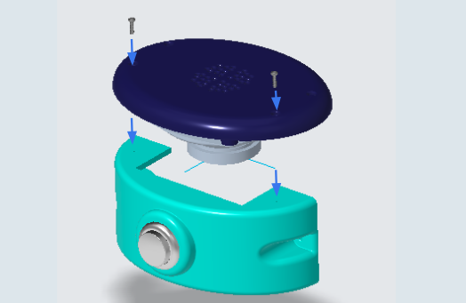
Step 11
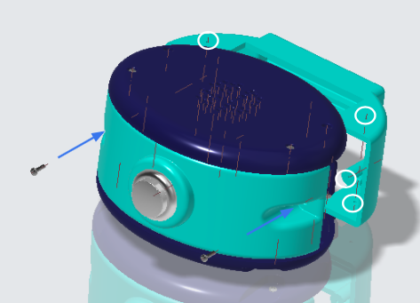
Grab the upper case subassembly and the front cover with the attached button. Use two machine screws and secure the upper case subassembly to the front cover as shown.
Step 12
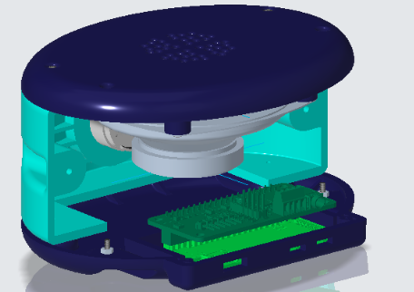
Take the bottom case subassembly and attach it to the aforementioned parts as shown.
Step 13
(Not pictured) Attach the wires from the speaker to the PCB as instructed, and use the given wires to attach the speaker to the PCB setup.
Step 14
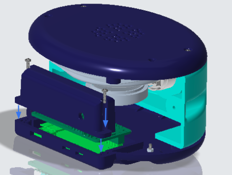
Take the circuit cover and two machine screws. Attach the circuit cover and align the holes of the cover to the holes of the bottom case. Insert the screws as shown.
Step 15
Take the back cover and tap all six screw holes before use. Next, take two machine screws and attach the back cover using the screws coming in from the front cover.
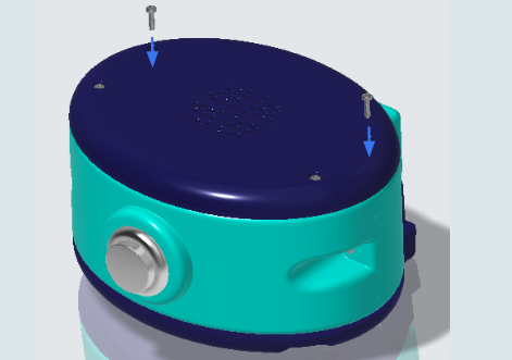
Step 16
Take two more machine screws and insert them through the upper case and into where the back cover would be.
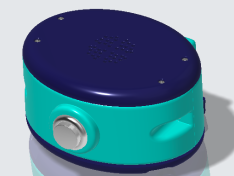
Step 17
Assembly complete! Enjoy your noisemaker.